Crack propagation investigation
A project aimed at understanding how cracks propagate or spread over time by studying the behavior and mechanics of cracks in materials or structures. My job as an engineer is to evaluate the crack propagation data obtained from the investigation and determine whether or not the crack is safe.
56
0

Introduction
This type of research is important in a variety of fields, including engineering, materials science, and physics, because it can assist researchers and practitioners in designing more durable and reliable structures, predicting failure modes, and developing effective repair and maintenance strategies. Finite element analysis, fracture mechanics, and experimental testing are some common methods used in crack propagation investigations.
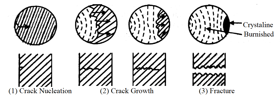
The concept of crack can be explained in the following three steps:
- Crack Nucleation: The formation of a small defect or flaw in the material is the first stage of the fracture process. This defect may have occurred during the manufacturing process or may have occurred during service as a result of factors such as cyclic loading, high stress concentrations, or environmental effects.
- Crack Propagation: Once a defect exists, it can grow or propagate as a result of external loads or stresses applied to the material. Depending on factors such as the loading rate, material properties, and crack size and shape, the crack growth process can be slow and steady or rapid and catastrophic. The crack can weaken the material, reduce its load-carrying capacity, and increase the risk of catastrophic failure as it grows.
- Fracture: The final stage of the fracture process occurs when the crack has grown to a critical size and the material can no longer support the applied load, resulting in catastrophic failure. This can lead to unexpected and sudden failure, with serious consequences in terms of safety, economic losses, and environmental impact. The type of fracture that occurs is determined by several factors, including the material properties, loading conditions, and the size and shape of the crack. Common fracture types include ductile, brittle, and fatigue.
Geometric parameters:
Overview:
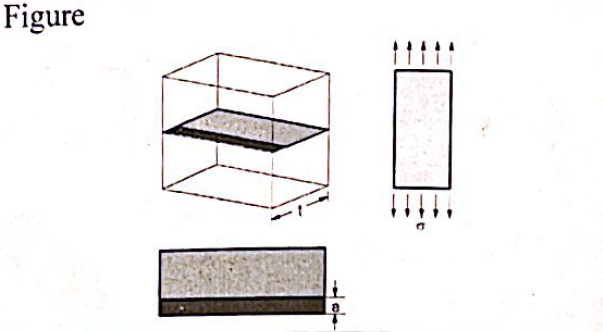
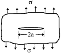
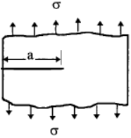
The stress intensity factor is generally determined by the applied stress, crack size, and geometry. Where Y is referred to as the geometry factor and represents the geometry of a crack system in relation to the applied load. This geometry factor is typically found in technical reference books.
Y = 1.0 for a central crack in an infinite plate:
Y = 1.12 for Edge crack in a semi-infinite body:
In general, if the edge crack is located in a finite-width strip, w, the correction factor becomes a function of (a/w):
Two calculated Y parameters available for the project,
Since the first condition is applicable we will progress with finding the first Y function:
Calculate stress intensity factor (SIF) [K]:
Validate the results,
Kic: is the fracture toughness of material which is obtained by determining the ability of material to withstand the load in the present of a sharp crack before failure. However, to validate of the K value simple equation will be introduced:
Approval Statement:
This is to certify that the plate under tension with a crack has been tested and found to be safe for its intended use in accordance with [Effect of Mean Stress on Fatigue Crack Growth Behavior of Stainless Steel 304L]. The evaluation included a thorough examination of the crack's size, location, as well as the material properties of the plate. The analysis was carried out using accepted engineering methods and calculations, as well as reasonable assumptions and data According to the evaluation results, the plate under tension with crack has sufficient structural integrity and is safe for its intended use.
At this time, no further action is required. To ensure continued safety, it is recommended that the plate be subjected to regular monitoring and maintenance. This approval is only valid for the evaluation's specific conditions and parameters, and it does not apply to any other situations or changes.


